SmartLock
Начну с того, что путь обуздания ESP8266_RTOS_SDK, а именно такой путь я избрал для себя, даётся не легко. Последней победой была оптимизация библиотеки RFID считывателя карт с STM на ESP. С чего и продолжилась история сего проекта умного замка, по совместительству и звонка.
Данная статья не является уроком. Я лишь описываю в ней свое устройство с открытым исходным кодом и его работу. что бы вы могли подчерпнуть некоторые идеи или реализации для своих проектов.
Технические описания будут представлены в репозиториях проектов, а здесь я вкратце опишу принципы и ресурсы.
“Мозгом” устройства является контроллер ESP8266 выполняющий роль валидатора карт, управления замком, звонка и связующего с внешним миром модуля. С этим ему помогают:
- плата считыватель RFID меток – MFRC522 подключенная по SPI
- модуль сенсорной кнопки работающий на расстоянии до 5 мм
- любой управляемый электронный замок
В исходном коде прошивки все не идеально, но я стараюсь совершенствоваться. Все части прошивки расположены в разных компонентах и независимы. Это значит, что есть компоненты:
lock_access– отвечает за предоставление доступа по картеlock_connect– отвечает за соединение замка с сетью и серверомlock_hardware– отвечает за управление железной частью замка (дверью, если так понятней)rc522– оптимизированная под целевой SDK библиотека связи с модулем считывателя RFID меток
С названием и назначением разобрались. Далее о независимости.. Каждый из компонентов запускается и работает параллельно, а данные обмениваются посредством функционала RTOS. Таким образом замок не перестанет работать, если вдруг с Wi-Fi случится беда. А попасть домой, если модуль считывателя карт даст сбой, можно будет через телефон и сервер MQTT подав модулю сигнал отрыть дверь.
Сейчас, за неимением практики применения, модуль железной части замка не откалиброван под реальные задачи, но предусмотрены функции открытия и закрытия замка хотя сейчас большинство замков работают по принципу открытия и защелкивания, но у меня нет финансовой возможности организовать поле для применения на практике. В дальнейшем будут усовершенствования основанные на реальных событиях так сказать.
Разберем некоторые возможности компонентов
Каждый компонент имеет минимум 1 функцию – функцию инициализации. Она в конечном итоге запускает задачу с логикой обработки запросов компонентом. Задача сделана для того, что бы легко добавлять новы компоненты без изменений старых.
lock_access
Этот компонент инициализирует модуль считывателя карт и его задача в цикле опрашивать наличие карты и считывать ее UID для идентификации. При идентфикации правильной карты модуль записывает в общую группу событий (возможности RTOS) сигнал о получении доступа по карте, иначе – сигнал о блокировке доступа по карте.
Дабы не “задалбывать” считыватель, в цикле предусмотрена задержка в 100 мс. что на отклик ощутимо не влияет.
lock_connect
В этом компоненте 2 функции инициализации для Wi-FI и MQTT.
В инициализации Wi-Fi прошивка пытается соединиться с точкой доступа, имя и пароль которой , на данный момент, прописываются при компиляции прошивки. При удаче, записывает в отдельную группу событий бит о подключении.
MQTT создает задачу, в которой ждет соединения с точкой доступа. После подключения, производится попытка соединения с брокером MQTT.
Когда замок получает сообщение, прошивка посылает соответствующий бит в группу событий всей прошивки. Например: если Вы захотите открыть замок с телефона, на замок придет сообщение и попадет в группу.
Также задача MQTT ждет события, которое должна обработать. Это события получения/отказа доступа по карте и событие нажатия на звонок. Соответственно Ваш телефон или другая часть “умного дома” получит уведомления об этом обытии.
lock_hardware
На данный момент отвечает за 2 устройства: сам замок и звонок (кнопку). В инициализации включаются соответствующие выводы модуля.
В задаче компонент ждет события от компонента lock_access о получении доступа или компонента lock_connect о запросе на открытие двери по MQTT.
Также тут происходит обработка события нажатия кнопки, по которому компонент оставляет соответствующий бит в группе событий.
rc522
Работа этого компонента будет описана в соответствующей его репозиторию вики страничке.
Схема
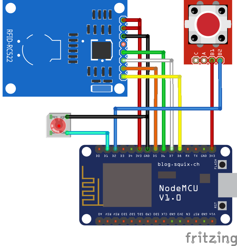
Считыватель подключается по интерфейсу SPI. Пин для управления щеколдой (эл.замком) сейчас является D1, а для отслеживания нажатия клавиши звонка испоьзуется пин D2.
Заключение
В заключении скажу, что это начало более грандиозного проекта, работа над которым будет продолжена ни без поддержки сайтом Ardino Geek
Дальнейшая разработка будет направлена на “умное” освещение и приборы, и дешовую сеть, управляющую ими.
Иходники
Спасибо за внимание! Не болейте.