DS18B20 – это цифровой датчик температуры. Датчик очень прост в использовании. Во-первых, он цифровой, а во вторых – у него всего лишь один контакт, с которого мы получаем полезный сигнал. То есть, вы можете подключить к одному Arduino одновременно огромное количество этих сенсоров. Пинов будет более чем достаточно. Мало того, вы даже можете подключить несколько сенсоров к одному пину на Arduino! Но обо всем по порядку.
Arduino датчик температуры DS18B20
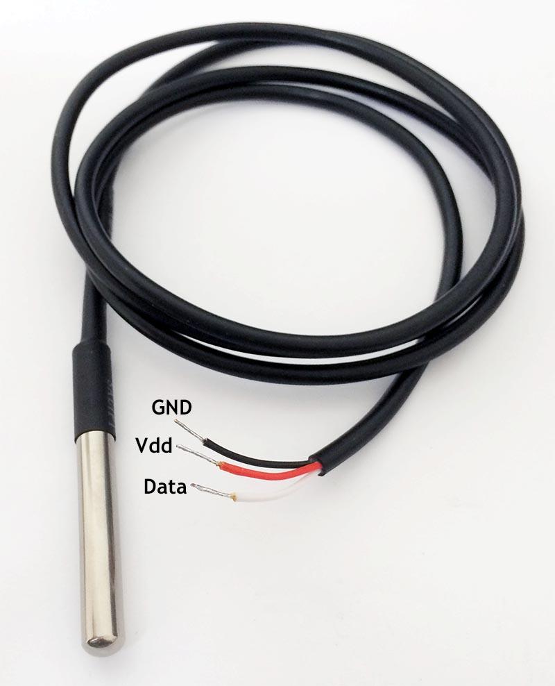
DS18B20 имеет различные форм-факторы. Так что выбор, какой именно использовать, остается за вами. Доступно три варианта: 8-Pin SO (150 mils), 8-Pin µSOP, и 3-Pin TO-92. Серфинг по eBay или Aliexpress показывает, что китайцы предлагают версию TO-92 во влагозащищенном корпусе. То есть, вы можете смело окунать подобное чудо в воду, использовать под дождем и т.д. и т.п. Эти сенсоры изготавливаются с тремя выходными контактами (черный – GND, красный – Vdd и белый – Data).
Различные форм-факторы датчиков DS18B20 приведены на рисунке ниже.

Модель DS18B20 во влагозащищенном корпусе:

DS18B20 удобен в использовании. Запитать его можно через контакт data (в таком случае вы используете всего два контакта из трех для подключения!). Сенсор работает в диапазоне напряжений от 3.0 В до 5.5 В и измеряет температуру в диапазоне от -55°C до +125°C (от -67°F до +257°F) с точностью ±0.5°C (от -10°C до +85°C).
Еще одна крутая фича: вы можете подключить параллельно вплоть до 127 датчиков! и считывать показания температуры с каждого отдельно. Не совсем понятно, в каком проекте подобное может понадобится, но подключить два сенсора и контролировать температуру в холодильнике и морозильной камере можно. При этом вы оставите свободными кучу пинов на Arduino… В общем, фича приятная.
Что вам понадобится для контроля температуры с помощью Arduino и DS18B20
- Естественно, вам необходима Arduino IDE;
- Библиотека OneWire library, которая значительно облегчает работу с Arduino и датчиком DS18B20;
- Скетч…
Скачать Arduino IDE можно с официального сайта Arduino.
Библиотеку OneWire Library можно скачать на OneWire Project Page (желательно скачивать последнюю версию библиотеки).
- Как минимум один цифровой датчик температуры DS18B20;
- Контроллер Arduino (в данном примере используется Arduino Uno);
- 3 коннектора;
- Монтажная плата (Breadboard);
- USB кабель для подключения Arduino к персональному компьютеру.
USB кабель необходим для программирования нашего Arduino. После того, как вы “зальете” скетч на плату, можно подключать ее к отдельному источнику питания.
Подключение DS18B20 к Arduino
Датчик подключается элементарно.
Контакт GND с DS18B20 подключается к GND на Arduino.
Контакт Vdd с DS18B20 подключается к +5V на Arduino.
Контакт Data с DS18B20 подключается к любому цифровому пину на Arduino. В данном примере используется пин 2.
Единственное, что необходимо добавить из внешней дополнительной обвязки – это подтягивающий резистор на 4.7 КОм.
Схема подключения DS18B20 к Arduino показана ниже (в скетче, который будет приведен ниже, проверьте строки 10 и 65. В них указаны пины, к которым вы подключали контакт сигнала с датчика и режим питания!):

На рисунке ниже приведена фотография нашей простой схемы “в жизни”.

Паразитное и обычное питание
Есть альтернативный вариант подключения – так называемое “паразитное” подключение. В этом случае мы не будем подключать пин +5V к пину Vdd на датчике DS18B20. Вместо этого мы подключим контакт Vdd с датчика DS18B20 к GND. Преимущества такого подключения очевидны: нам понадобится всего два коннектора!
Недостатком такого подключения является ограничение количества одновременно подключаемых сенсоров. Кабели для подключения должны быть максимально короткими!
В общем, с “паразитным” подключением надо быть аккуратнее и лучше его все-таки не использовать. Результаты (значения температур) могут оказаться самыми неожиданными.
Скетч для Arduino и сенсора DS18B20
Установливаем библиотеку OneWire Library
После того как вы скачали архив с библиотекой, ее надо импортировать. Для этого в Arduino IDE выберите пункт “Sketch” – “Import Library” – “Add Library” и выберите архив, который вы скачали. Если у вас возникли проблемы, с установкой библиотеки, ознакомьтесь с инструкцией по установке библиотек в Arduino.
Загружаем скетч на Arduino
Скетч, который представлен ниже, есть в библиотеке OneWire, в категории examples. Перейдите в “File” – “Examples” – “OneWire” и выберите пример “DS18x20_Temperature”. Код программы представлен ниже.
Данный пример использует библиотеку OneWire Library, для того, чтобы собрать данные со всех подключенных датчиков температуры DS28B20 (как подключить несколько сенсоров описано в конце статьи) и отобразить их в окне серийного монитора Arduino IDE.
В окне серийного монитора вы увидите примерно следующее:
ROM = 28 88 84 82 5 0 0 6A
Chip = DS18B20
Data = 1 56 1 4B 46 7F FF A 10 D1 CRC=D1
Temperature = 21.37 Celsius, 70.47 Fahrenheit
No more addresses.
ROM = 28 88 84 82 5 0 0 6A
Chip = DS18B20
Data = 1 56 1 4B 46 7F FF A 10 D1 CRC=D1
Temperature = 21.37 Celsius, 70.47 Fahrenheit
No more addresses.
ROM = 28 88 84 82 5 0 0 6A
Chip = DS18B20
Data = 1 56 1 4B 46 7F FF A 10 D1 CRC=D1
Temperature = 21.37 Celsius, 70.47 Fahrenheit
No more addresses.
Обычное или паразитное питание?
DS18B20 может работать в обычном или в так называемом “паразитном” режиме. В обычном режиме для подключения используется 3 коннектора, в “паразитном” режиме – в его лишь 2.
Вам надо настроить правильный режим в скетче, чтобы снять достоверные показания с датчика:
- Для “паразитного” режима в строке 65 надо указать: ds.write(0x44, 1);
- Для обычного режима в строке 65 указывается: ds.write(0x44);
Убедитесь, что вы указали корректные пины!
В строке 10, где указано “OneWire ds(2);” устанавливается пин, к которому подключен контакт data с сенсора.
В этом примере использован пин 2, но значения пина по умолчанию в примере OneWire стоит на 10. Можно использовать и его.
#include <OneWire.h>
// пример использования библиотеки OneWire DS18S20, DS18B20, DS1822
OneWire ds(2); // на пине 10 (нужен резистор 4.7 КОм)
void setup(void) {
Serial.begin(9600);
}
void loop(void) {
byte i;
byte present = 0;
byte type_s;
byte data[12];
byte addr[8];
float celsius, fahrenheit;
if ( !ds.search(addr)) {
Serial.println("No more addresses.");
Serial.println();
ds.reset_search();
delay(250);
return;
}
Serial.print("ROM =");
for( i = 0; i < 8; i++) {
Serial.write(' ');
Serial.print(addr[i], HEX);
}
if (OneWire::crc8(addr, 7) != addr[7]) {
Serial.println("CRC is not valid!");
return;
}
Serial.println();
// первый байт определяет чип
switch (addr[0]) {
case 0x10:
Serial.println(" Chip = DS18S20"); // или более старый DS1820
type_s = 1;
break;
case 0x28:
Serial.println(" Chip = DS18B20");
type_s = 0;
break;
case 0x22:
Serial.println(" Chip = DS1822");
type_s = 0;
break;
default:
Serial.println("Device is not a DS18x20 family device.");
return;
}
ds.reset();
ds.select(addr);
ds.write(0x44); // начинаем преобразование, используя ds.write(0x44,1) с "паразитным" питанием
delay(1000); // 750 может быть достаточно, а может быть и не хватит
// мы могли бы использовать тут ds.depower(), но reset позаботится об этом
present = ds.reset();
ds.select(addr);
ds.write(0xBE);
Serial.print(" Data = ");
Serial.print(present, HEX);
Serial.print(" ");
for ( i = 0; i < 9; i++) { // нам необходимо 9 байт
data[i] = ds.read();
Serial.print(data[i], HEX);
Serial.print(" ");
}
Serial.print(" CRC=");
Serial.print(OneWire::crc8(data, 8), HEX);
Serial.println();
// конвертируем данный в фактическую температуру
// так как результат является 16 битным целым, его надо хранить в
// переменной с типом данных "int16_t", которая всегда равна 16 битам,
// даже если мы проводим компиляцию на 32-х битном процессоре
int16_t raw = (data[1] << 8) | data[0];
if (type_s) {
raw = raw << 3; // разрешение 9 бит по умолчанию
if (data[7] == 0x10) {
raw = (raw & 0xFFF0) + 12 - data[6];
}
} else {
byte cfg = (data[4] & 0x60);
// при маленьких значениях, малые биты не определены, давайте их обнулим
if (cfg == 0x00) raw = raw & ~7; // разрешение 9 бит, 93.75 мс
else if (cfg == 0x20) raw = raw & ~3; // разрешение 10 бит, 187.5 мс
else if (cfg == 0x40) raw = raw & ~1; // разрешение 11 бит, 375 мс
//// разрешение по умолчанию равно 12 бит, время преобразования - 750 мс
}
celsius = (float)raw / 16.0;
fahrenheit = celsius * 1.8 + 32.0;
Serial.print(" Temperature = ");
Serial.print(celsius);
Serial.print(" Celsius, ");
Serial.print(fahrenheit);
Serial.println(" Fahrenheit");
}
Как подключить несколько сенсоров DS18B20 к Arduino?
Вы можете подключить несколько цифровых датчиков температуры DS18B20 параллельно. При этом библиотека OneWire library позволит вам считывать данные со всех датчиков одновременно.
Ниже описаны два метода подключения сенсоров.
Для большого количества сенсоров (больше 10), надо использовать резисторы с меньшим сопротивлением (например, 1.6 КОм или даже меньше).
Кроме того, если вы подключаете параллельно более 10 датчиков, могут возникнуть проблемы (погрешности при съеме показаний). Поэтому рекомендуется устанавливать дополнительный резистор сопротивлением 100…120 Ом между контактом data на Arduino и data на каждом сенсоре!
Результат работы предыдущего скетча с двумя подключенными сенсорами может выглядет примерно следующим образом:
ROM = 28 88 84 82 5 0 0 6A
Chip = DS18B20
Data = 1 51 1 4B 46 7F FF F 10 FE CRC=FE
Temperature = 21.06 Celsius, 69.91 Fahrenheit
ROM = 28 DA CA 27 5 0 0 49
Chip = DS18B20
Data = 1 4E 1 4B 46 7F FF 2 10 D9 CRC=D9
Temperature = 20.87 Celsius, 69.57 Fahrenheit
No more addresses.
Выбираем правильный сенсор
Было бы неплохо знать, с какого именно сенсора вы получаете данные, когда вы используете параллельно несколько датчиков. Как это сделать?
Серийный номер
Так как датчики цифровые, у каждого из них есть индивидуальный серийный номер, который можно использовать для опознавания того или иного сенсора. Вроде бы все просто. Но… нам ведь надо предварительно определить эти серийные номера, прежде чем использовать их для опознавания сенсора, правильно?
Вы могли обратить на примерах выше, что скетч выдает нам данные в виде 64-битного серийного номера – значение “ROM”. Например:
28 88 84 82 5 0 0 6A или 28 DA CA 27 5 0 0 49 в примере выше.
Не забывайте, если вы используете одновременно большое количество датчиков (10 и больше), надо добавить резисторы 100 … 120 Ом между контактами data с сенсора DS18B20 и пином data на Arduino (для каждого датчика!).
Нормальный режим питания
Ниже показана схема параллельного подключения нескольких сенсоров с использованием трех контактов.

Паразитный режим питания
В “паразитном” режиме контакт Vdd остается фактически не задействован. Питание датчика осуществляется через контакт data.

Оставляйте Ваши комментарии, вопросы и делитесь личным опытом ниже. В дискуссии часто рождаются новые идеи и проекты!
Ссылка на источник: http://arduino-diy.com/arduino-tsifrovoy-datchik-temperatury-DS18B20